Olympus 35-S II

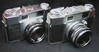
The Olympus 35-S was a series of fixed lens rangefinder cameras made by Olympus in the 1950's. The two cameras shown here are the later versions. The camera on the left has the f/1.8 lens while the camera on the right has the f/2.8 lens. Both lenses are coated multi-element lenses and are very high quality. Olympus also produced a version with a f/2 lens.

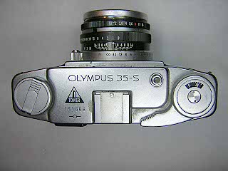
The f/1.8 lens model has the Tower brand logo on top indicating it was manufactured for sale by Sears, Roebuck & Co. Some variations of these cameras have a self-timer lever on the front panel. The absence of the lever indicates this is a later model. Because the self-timer lever was removed, some people think the later versions lack a self-timer. Actually, the shutter has a self-timer that is engaged when the flash synch switch is set to the "V" position.

The focus control ring has a convienent button that makes focusing with a finger or thumb very easy. The exposure controls are easily accesible on the lens barrel, and unlike some later Olympus models, are big enough to be easy to use.

Both cameras have Seikosha shutters with a light value scale. This scale allowed using a meter that indicates light values instead of shutter/aperture combinations.

Overall, these cameras are a real pleasure to shoot with. If you are not sure of your repair skills, it would definitely be worth paying a professional repairman to do a CLA on one of these cameras, especially if the camera is in mint cosmetic condition.

Both of these cameras came to me with stiff focus, sluggish shutter and dirty viewfinder. Lubricating the focus requires an almost complete disassembly of the camera followed by cleaning and lubricating. Fortunately, this is an easy design to work on.


To remove the top cover, open the back and hold the rewind shaft while unscrewing the rewind knob. Unscrew the slotted retaining ring under the rewind knob.

Remove the pin face screw on the wind knob then lift the knob and the counter mask off. The mask may come off with the lever.

Remove the screw at the right side of the top cover and lift the cover off

Remove the two brass screws on top of the rangefinder and remove the black cover. This will allow access to the rangefinder lenses for cleaning. To remove the rangefinder from the camera, remove the two screws on the left side and one screw behind the center mirror.

To remove the film counter, unhook the spring and lift the counter dial off. The pin on the bottom of the counter dial sits against the stop at the front of the camera. The start position of the counter can be adjusted by loosening the screw in the stop and sliding it back and forth.


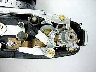
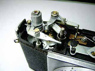
These two pictures show detail of the film counter and double exposure prevention ratchet. I removed these parts in order to clean under the film counter. Normally, there is no need to remove these levers.

To remove the bottom, unscrew the two screws in the bottom cover and lift the cover off. The rewind release button falls out.

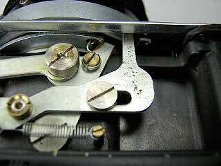
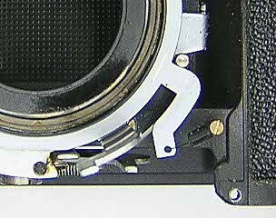
This picture shows a detail of the film wind mechanism. Note how the spring on the rack fits into a hole in the cocking lever that surrounds the shutter. On reassembly, this spring must be reinserted into the hole.

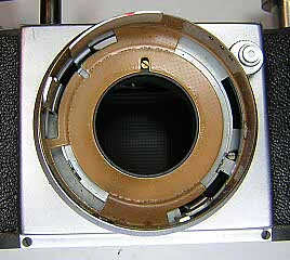
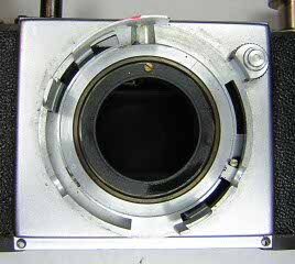
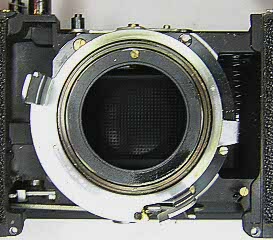
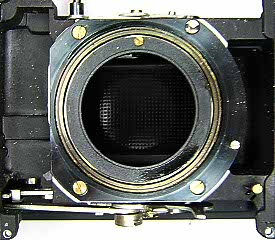
Open the camera back and unscrew the shutter jamb nut. The entire shutter and lens assembly lifts off together.

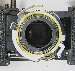
Remove the black tube that goes around the shutter. You need to lift and then rotate the tube slightly to clear the various operating levers.

Back out the set screws in the focus scale and lift the scale off. Mark the infinity position of the focus control ring, then back out the set screws in the ring and lift it off. Remove the screws in the front cover and lift the cover off.

Remove the brass retaining ring by inserting a pointed tip spanner in the holes and unscrewing it.

Unhook the spring on the cocked indicator and remove the indicator ring.

Remove the steel retaining ring by inserting a pointed tip spanner in the holes and unscrewing it. Lift off the cocking lever, spacer and release lever.

Remove the three brass screws and the infinity stop post then lift the focusing helicoid off. The infinity post screws into the camera body. On this camera there are two slots at the bottom of the post. I made a spanner to remove this post by cutting away the middle of a screwdriver leaving two long points.

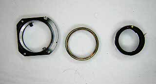
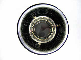
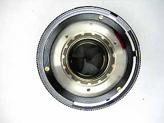
Separate the helicoid parts. Unscrew the brass focus ring until the inner helicoid barrel slips off the posts. Note this position for reassembly. Continue unscrewing the inner and outer parts noting the number of turns and position where the two separate. On reassembly, it is important to start the parts back on the same thread so that the marked infinity position is correct.

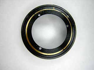
Unscrew the faceplate from the front lens and then unscrew the front lens assembly. The faceplate has two small slots in it for a spanner. I used a rubber stopper as a friction tool instead in order to avoid damage to the ring. With the lens out, remove the three brass screws and lift the aperture control ring out.

If needed, turn the aperture control ring over and remove the retaining ring on the back. This will allow separating the filter ring from the aperture ring for cleaning and repair and lubrication of the click stop.

Remove the three brass screw from the shutter speed ring and lift the ring off.

Remove the lock screw and then unscrew the serated retaining ring and lift the speed setting cam off.

Notes

Focus Adjustment

To adjust the focus, turn the focus ring until the lens is focused at infinity. Backout the set screws in the focus scale and lift the scale up to expose the screws in the focus ring. Back out the screws in the focus ring and turn the focus ring against the infinity stop. Retighten the screws on each ring. Make sure the focus scale is sitting on the infinity mark.

Rangefinder Adjustment

To adjust horizontal alignment, open the back and remove the cover screw at the top of the film gate. Set the lens to infinity then nsert a small flat blade screwdriver into the hole and turn the adjustment screw until the rangefinder images are aligned. Replace the cover screw.

To ajust the vertical alignment, pry off the cover plate on the accessory shoe to get access to the adjustment screw. The vertical alignment on my camera did not need to be adjusted. It appears that you turn the small screw to move the bracket on the mirror. It may be necessary to loosen the large screw first. There is also a screw on the back of the mirror that may have an effect on mirror position as well. Since my camera did not need to be adjusted, I did not determine which of these needs to be adjusted.

Links: