Rim Set Compur
The Compur shown here is an earlier (1930s) rim set version. It is called a "rim set" because
the speed is set by moving the large ring underneath the cover. This is a change from the
earlier dial set model where the speed was set with a small dial at the top.
This model is nearly identical in operation to the later Compur Rapid,
but has a slightly different disassembly sequence. This shutter is from a 6x9 format folding camera. The camera lacks
a manufacturer's name or model, but appears to be a Certo model.
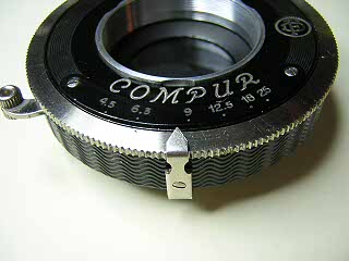 |
Remove the front and rear lens elements from the shutter.
To remove the cover, remove the screw in the aperture indicator and lift the pointer off.
Remove the two screws in the aperture scale and lift the scale off.
|
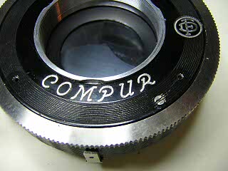 |
Underneath the aperture scale is a stop screw. Remove this screw and then rotate the cover until the
lips on the cover match the cutouts in the lens opening. The cover will then lift off. You may need to slide
a screwdriver tip under the edge and lift the cover if it will not fall off by itself.
|
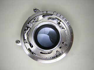 |
Lift the speed setting ring off the shutter. Note the position of the pins that are fitted into the slots in the speed setting ring.
On reassembly, these pins need to sit in their respective slots.
Note: Once the speed setting ring is off, you should not attempt to wind the shutter.
The center cocking ring will pop up if the shutter is wound or triggered with the cover off.
|
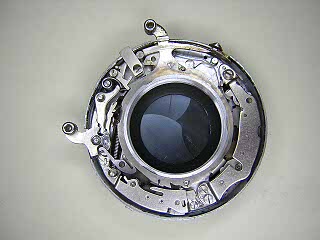 |
Note the position of the cocking ring in relationship to the levers on the slow speed assembly,
latch, B lever, and booster spring. All of these points interact with tabs on the cocking ring
and control the operation of the shutter. On reassembly, you need to insure each of the tabs on the
cocking ring is back in place.
To remove the cocking ring, unhook the spring attached to the end of the slow speed assembly,
lift up and rotate the ring clockwise until the spring is clear.
Most of the time you can flush clean the shutter without any further disassembly. However,
if the blades have oil on them, it is best to remove the blades and clean them by wiping them off.
It isn't necessary to remove the two escapement assemblies. However, you must remove
at least one of them if you want to remove the blade operating ring later.
It is best to leave the slow speed assembly in place (right, middle in the image). Adjusting its position
in order to set the proper speed can be very tedious.
|
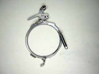 |
This image shows the underside of the cocking ring. Note there are two levers attached to the
ring. The lever at the bottom has to be pulled in when reinstalling the cocking ring. Make sure
these levers pivot easily and clean them if needed.
|
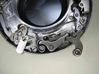 |
Before separating the shutter halves, you should remove the release and B levers (see image) since
these parts have springs that sit against the inside of the outer base and make it difficult to
put the shutter halves back together.
Start by removing the screw in the cable release socket and slide the socket out. Remove the screw
in the linking lever next to the cable release, and then remove the booster spring, and other levers.
Unhook, but don't remove, the spring on the blade operating lever. Remove the screw in the
lever and lift the lever out.
|
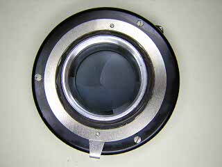 |
Turn the shutter over and remove the screws holding the shutter halves together.
Lift the back off of the inner base.
The outer base holds the diaphragm. Normally, you should try to flush clean the diaphragm
without removing the blades as the diaphragm can be very difficult to reassemble. If there is
old grease under the operating lever, turn the lever until you see the two screws holding the
lever to the base through the holes in the diaphragm cover. Remove the two screws and the
operating lever will fall off.
|
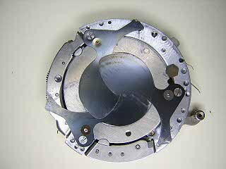 |
The three blades are held by a screw. Remove each screw in turn and lift the blade off.
The blade activating ring is held to the inner base with three tabs. To remove the ring,
remove the hex-head screw and then turn the ring until you can slide it out.
|
Notes
Speed adjustment is made by moving the slow speed assembly closer or further away from
the lens opening. As the assembly is moved inward, the shutter runs faster. Start by pushing
the assembly in as far as it will go, replace the speed setting ring and then test the shutter
at one second. If the shutter is too fast, move the assembly back slightly. Note that both ends
of the assembly can be moved. Sometimes it is necessary to adjust both ends to bring the shutter
up to speed.
The Compur can often run "dry" without any lubrication. However, on older shutters it
is sometimes necessary to add a tiny bit of oil to the bearings in the slow speed assembly. This
will help to reduce wear and prevent or overcome any oxidation.
Lubricate the speed setting cam, cover and diaphragm control lever where they rub against each other and the case.
|


