Seikosha
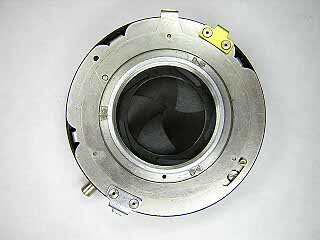
The Seikosha is a high quality, Japanese made shutter used on many Japanese rangefinder and TLR cameras. Minolta, Mamiya and Ricoh cameras often use this shutter or one of its variants. Several versions of the Seikosha and Seiko shutters were made. The shutter shown here has M/X-synch, self timer and a diaphragm with equidistant spacing of aperture for use with a LV scale. Disassembly of other models is similar to the shutter shown here. Later versions no longer have the M/X synch escapement.
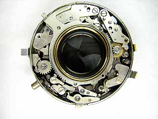 |
Remove the front and rear lens cells. Unscrew the wavy retaining nut and lift the speed setting rings off. (Note: On this particular camera, these parts were all removed with the lens barrel.) Lift off the trigger and latch levers. Note the position of their springs before removing. The spring on the latch lever sits against the B lever. Unhook the spring attached to the cocking ring from its anchor on the shutter base and lift the cocking ring off. |
 |
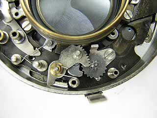
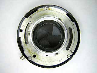
Lift out the gear on top of the main spring. Note or mark the position of the retard escapement assembly on the base. The position of the assembly controls the overall speed of the shutter. Remove the screws holding the assembly and lift it out. |
 |
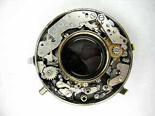
Remove the screws at each end of the self timer assembly and lift it out. The self timer is activated by pushing the gears in towards the cocking ring. On reassembly, the self timer must be properly engaged with the selector lever underneath (see next picture). |
 |
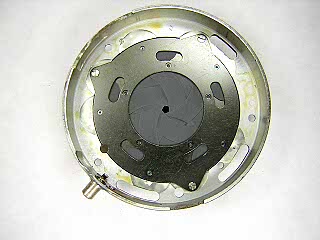
Remove the screw in the flash synchronizer cover and lift the cover off. Lift out the sector gear and star wheel. Remove the screw from the base under the star wheel and lift the base out. |
 |
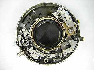
This picture shows a closeup of the flash synchronizer. |
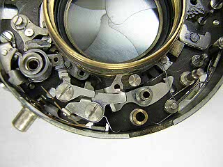 |
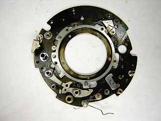
Remove the screw in the B lever and lift the lever and spring out. Remove the screw in the flash contact lever and lift the lever and spring out. Remove the flash contact. Unhook and remove the main spring. |
 |
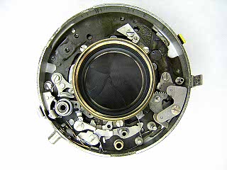
Unhook and remove the spring on the blade operating lever. Remove the screw and lift off the lever. |
 |
The remaining parts on the base are riveted or staked in place and are not removed. |
 |
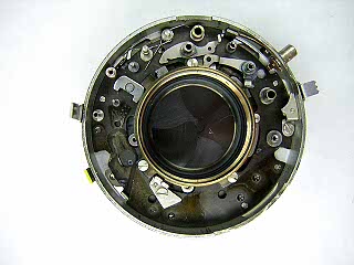
Turn the shutter over and remove the three screws around the lens opening. Lift off the aperture setting ring and flash M-X-V selector ring. |
 |
Remove the three screws holding the shutter halves together and then pull the shutter halves apart. Lift out the shutter blades noting the direction and order of the blades. |
 |
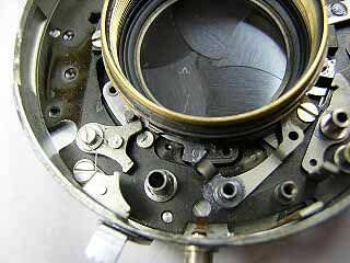
This picture shows the diaphragm. To remove the blades, remove the screws in the cover plate, lift the cover off and then lift the blades out. |
 |
To remove the blade activating ring, turn the shutter back over and remove the screws around the base of the lens opening. Lift the lens opening off and then lift off the blade activating ring. |
Notes
Speed adjustment is made by moving the slow speed assembly closer or further away from the lens opening. As the assembly is moved inward, the shutter runs slower.
Lubricate the speed setting cam, cover and diaphragm control lever where they rub against each other and the case.